Automatic Cable Winding
Retractible extension cords have helped to organize heavy-duty cables in garages/workshops for years now. Why hasn’t this technology been applied to the numerous cables we carry with us each day? Follow along for a live-look at my process to reverse engineer the mechanisms involved in this technology.
Prototype 1
Proof of Concept
Setting up the Basics
Determine Essential Components:
Bearings
Torsion Spring
Ratcheting mechanism with release
Cable Spool
Cable stop
Test Print 1:
Figure out proper tolerancing for press fitting bearings with 3D printed parts
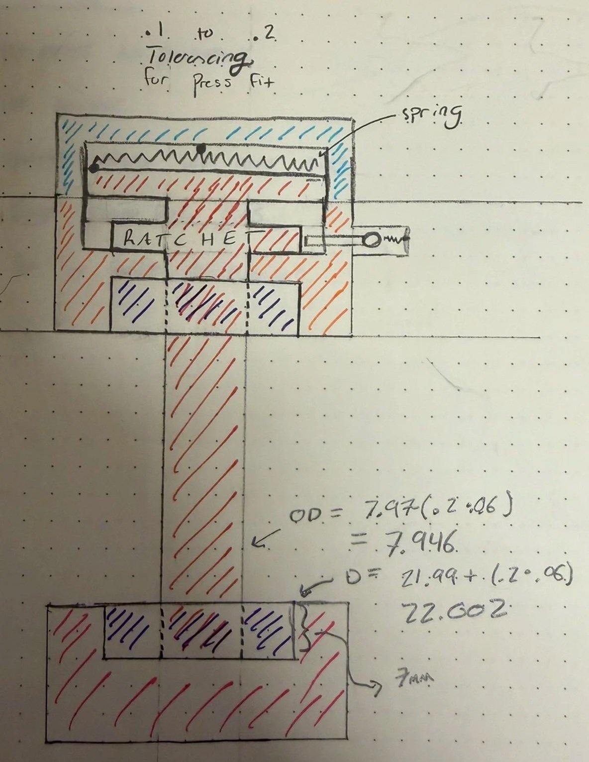

DFM, General Fit, General Geometry
Establish General Sizing
Establish diameter of case to hold torsion spring, fully winded cable
Make sure tolerances ok for smooth rotation
Make pieces simple, easy to assemble
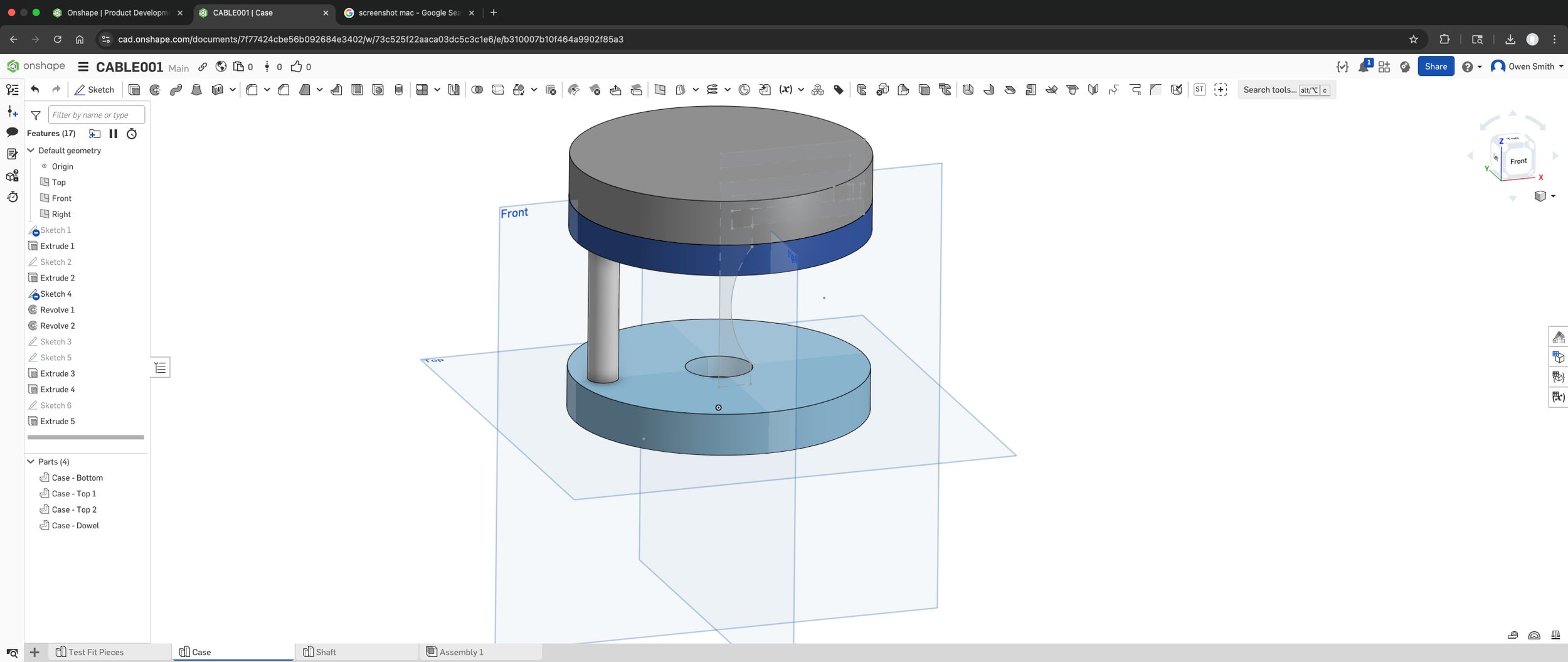
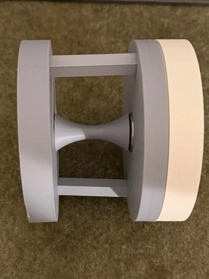
Test Print 2: Large Case Pieces
Simple design for large pieces. Allows for less re-prints to improve cost and time efficiency of mechanism design iteration
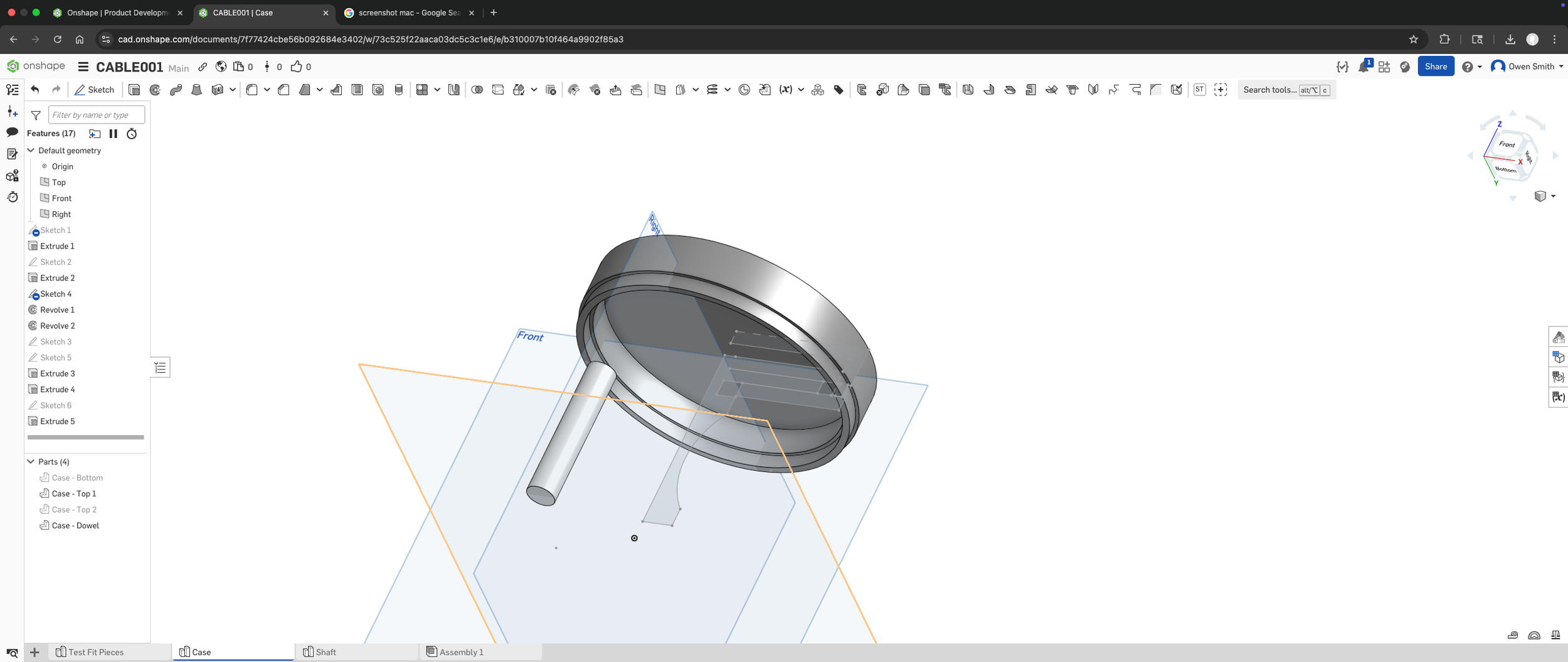

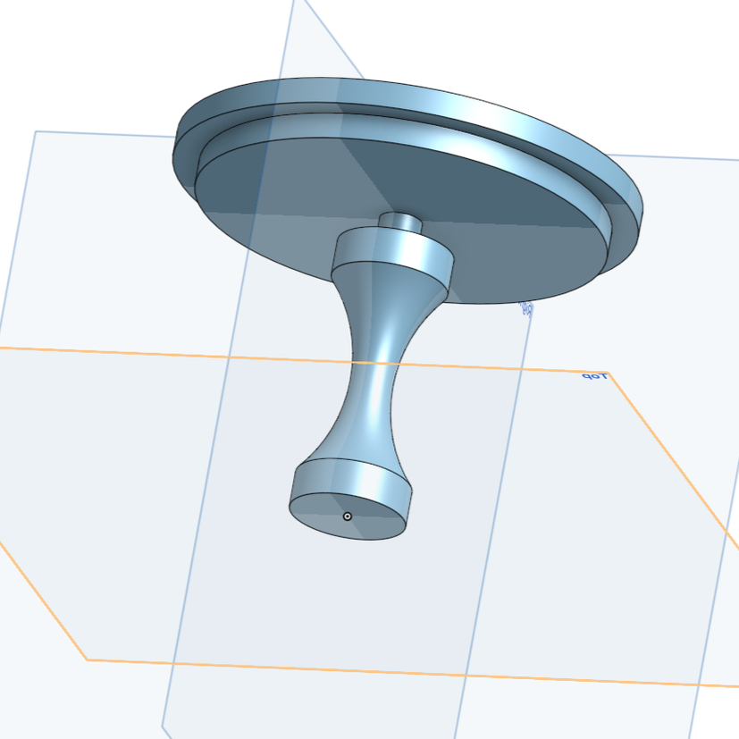
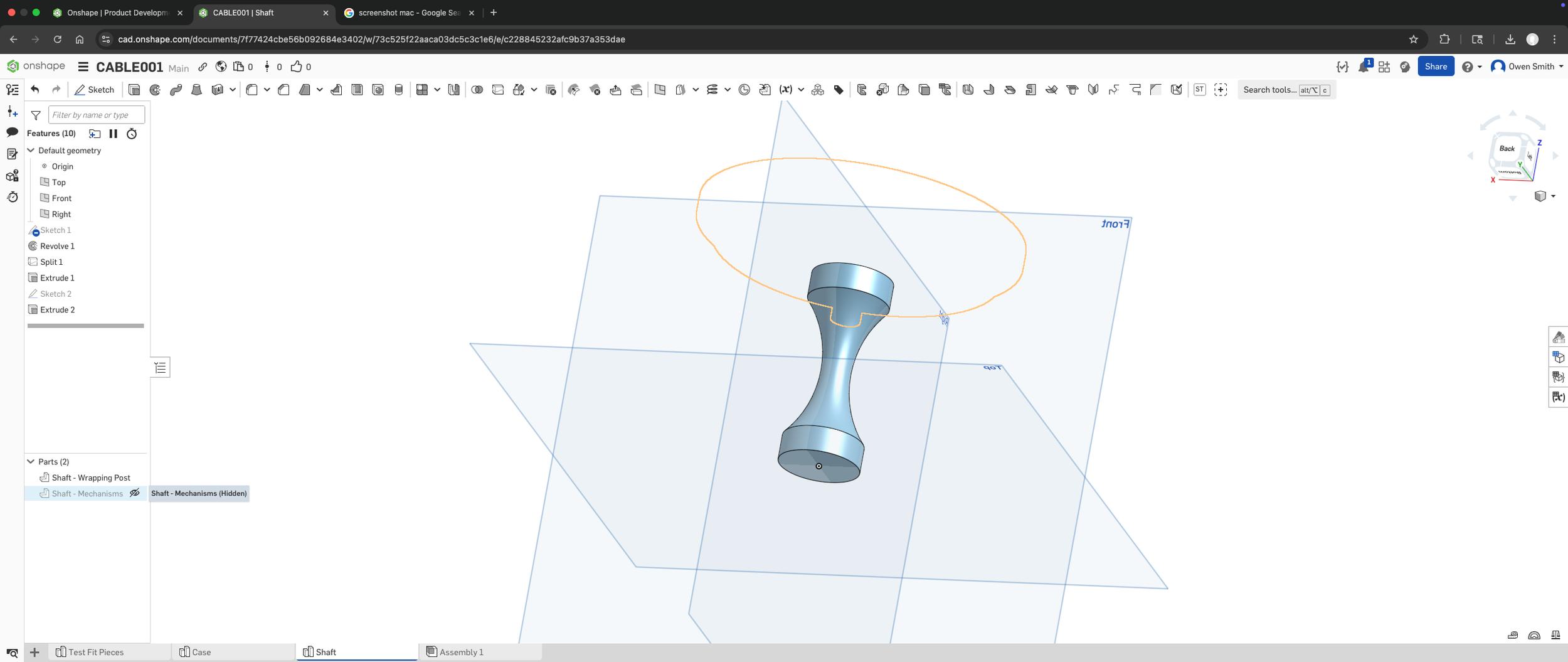
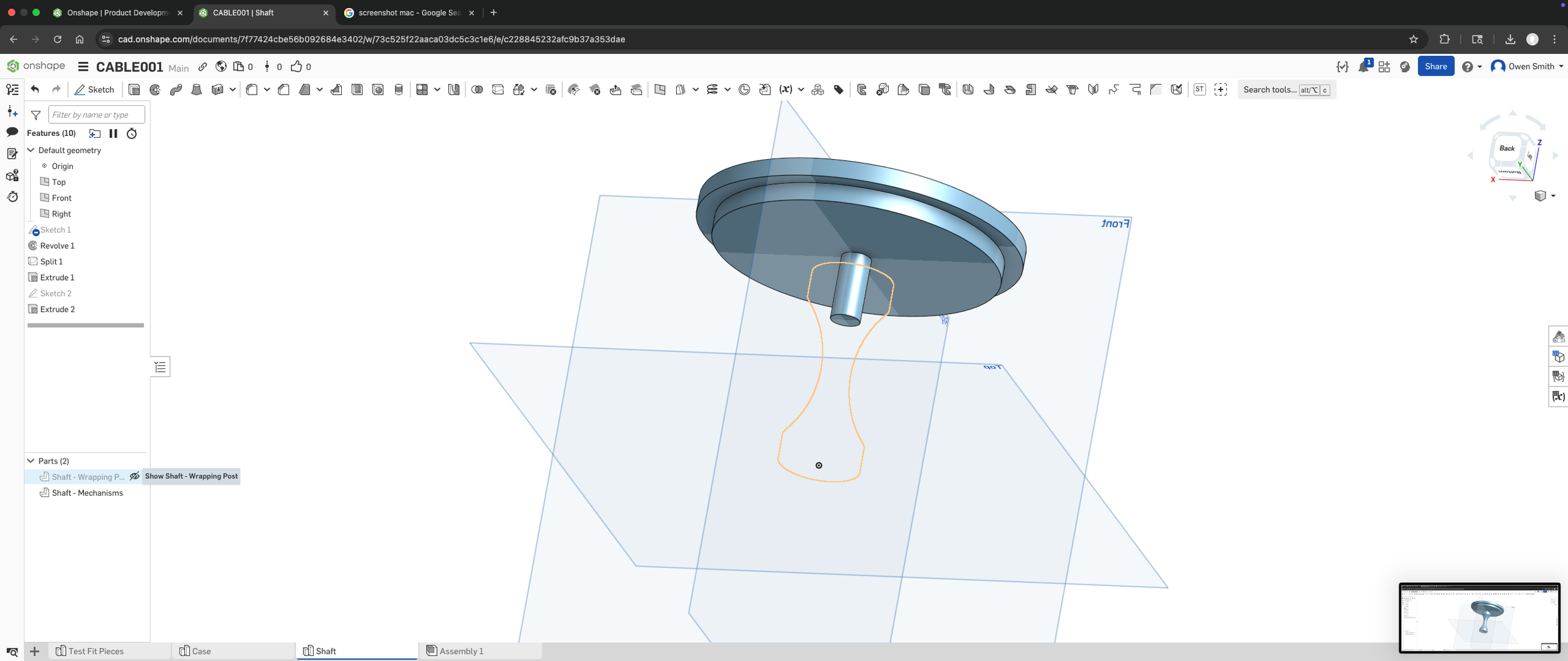
Spool Design
Determine how spool will interface with bearing and top case
Establish press fit Dimensions for 2 part spool
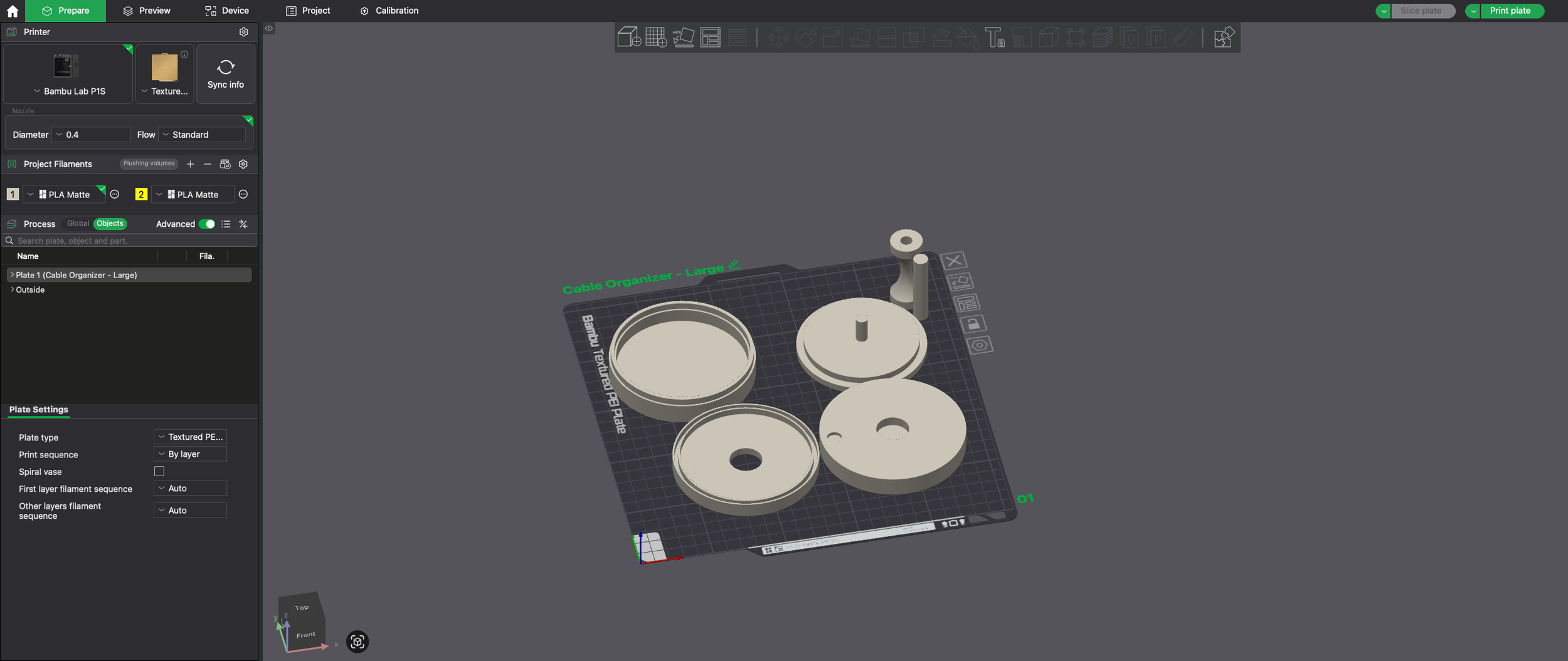
Test Fit, Draw Conclusions
Successes:
Proper diameter for full cable wind
Press fit dimensions for bearings
Easy to assemble, take apart, and print
Issues:
Spring Deformaility (switch to metal)
Design is clunky
Need ratcheting mechanism
Can drastically reduce pin-attachment style with heat set inserts/ screws
Prototype 2
Level up parts / Durability / Reduce Size / Address Cable Entry & Exit
V1 was fun, but now we’re really going for it!
Time To Get Serious
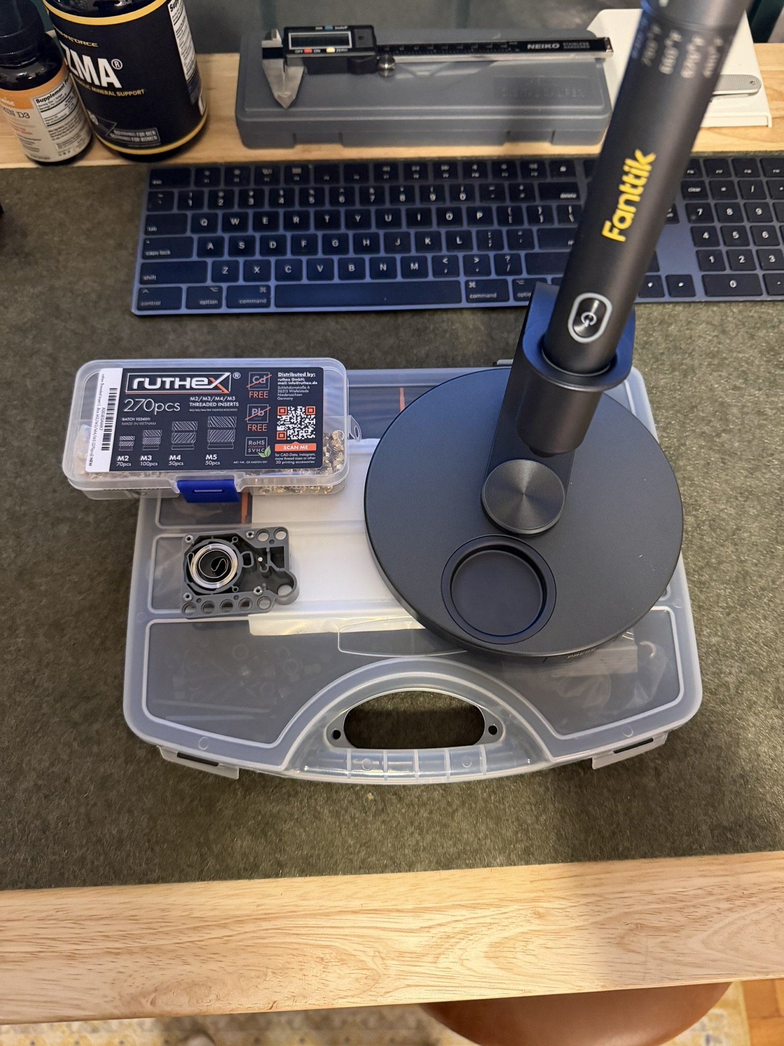
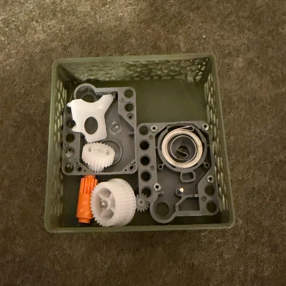
Procure Parts
Metal Torsion Spring from Lego Motor
Metal Pins from lego Motor
Basic spring for ratcheting mechanism
Heat Set Inserts (Metric)
Screw Set (Metric)
Soldering Iron
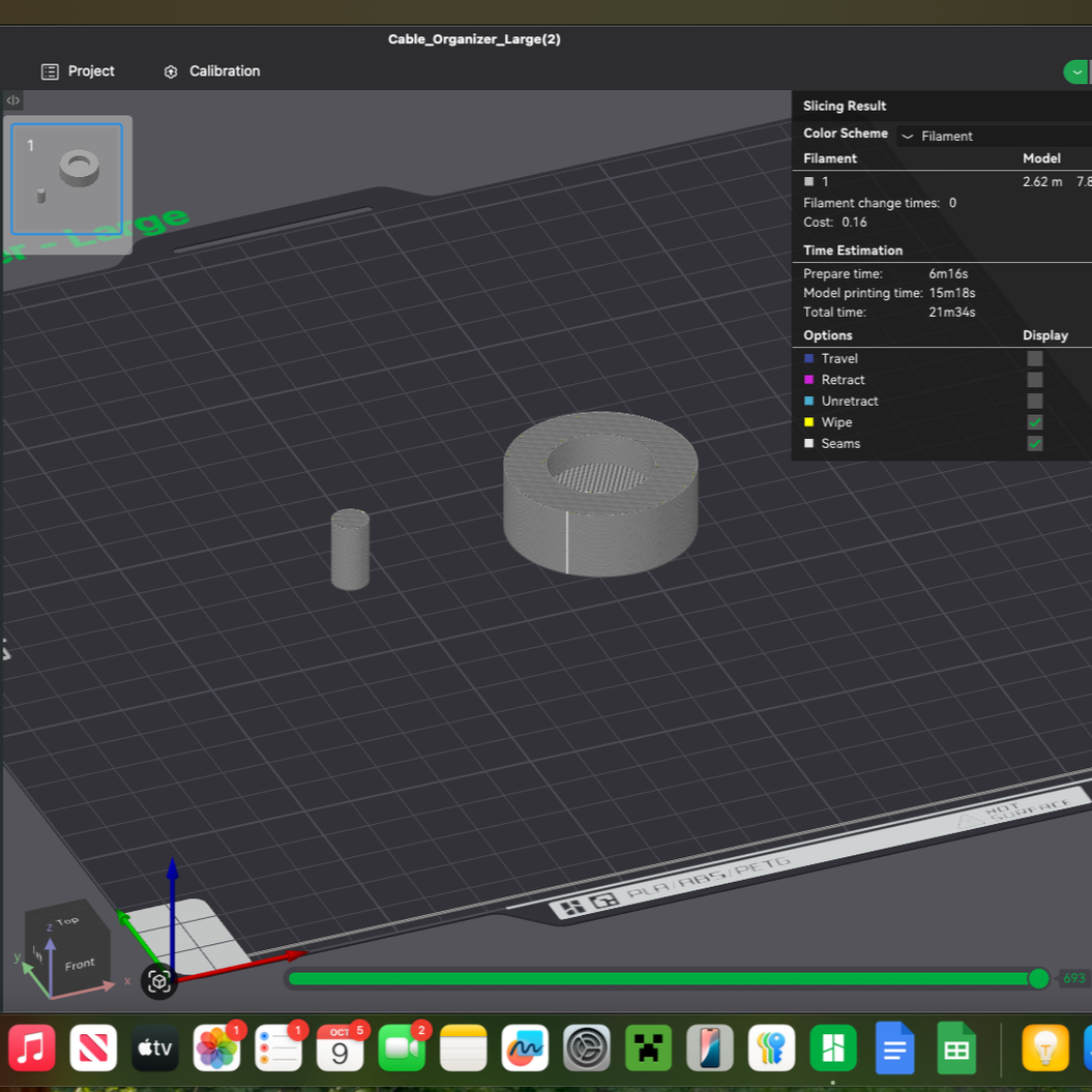
Test Print 1:
Figure out proper tolerancing for heat set inserts
~.5mm smaller diameter hole should suffice
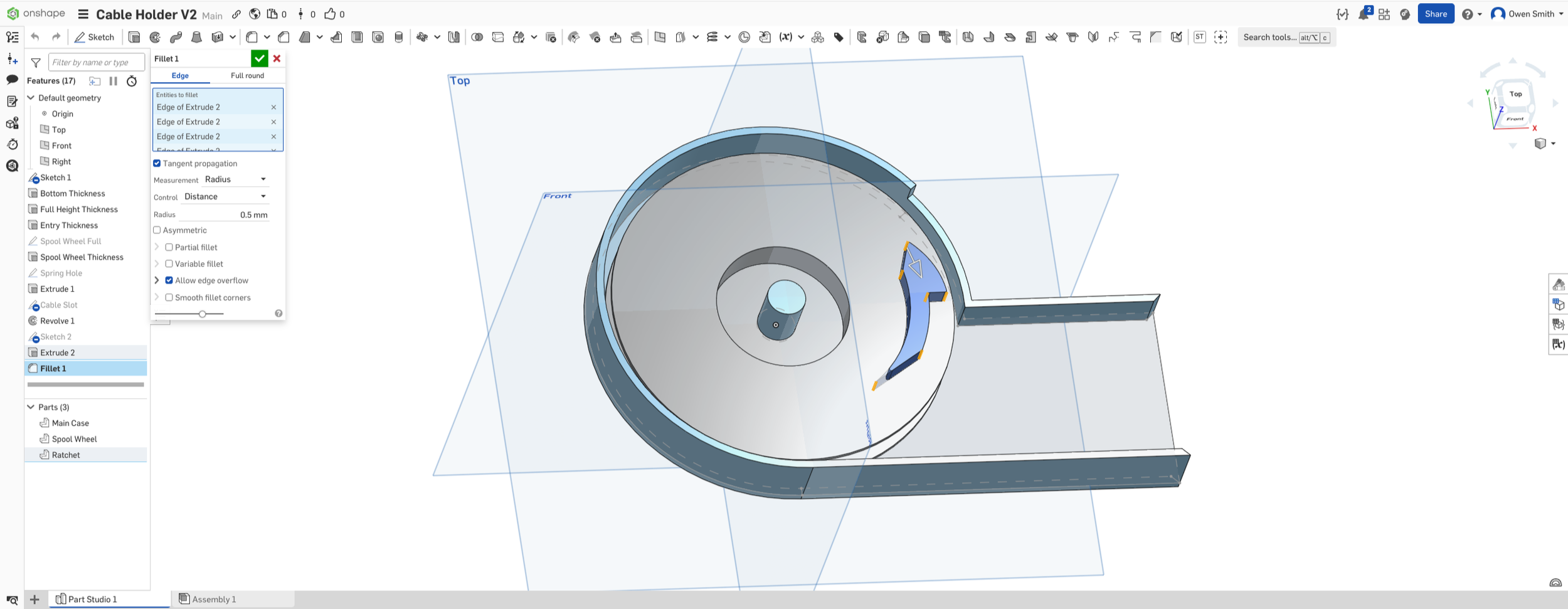
V2 Basic Shape / Concepts
Case
2 different heights of case
Clearance over top of spool wheel
reduced wall height for pawl to interface with teeth
Addition of a grid of holes
Allow for variable pin placement to accept spring + cam to optimize tension and ratchet interface (more on this later)
Pin going through center
Will house screw on top to fix top of case
Likely M2 or M3
Centerpoint of torsion screw
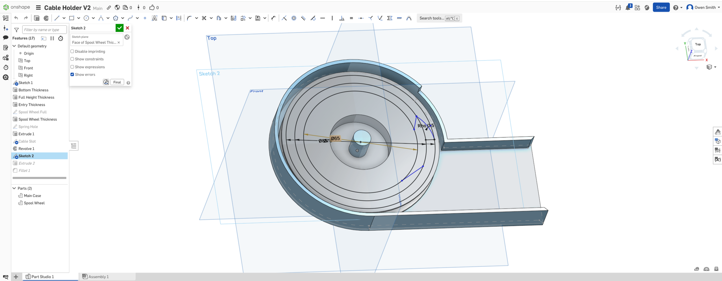
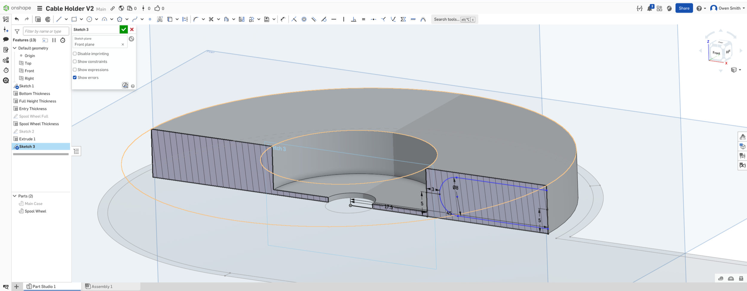
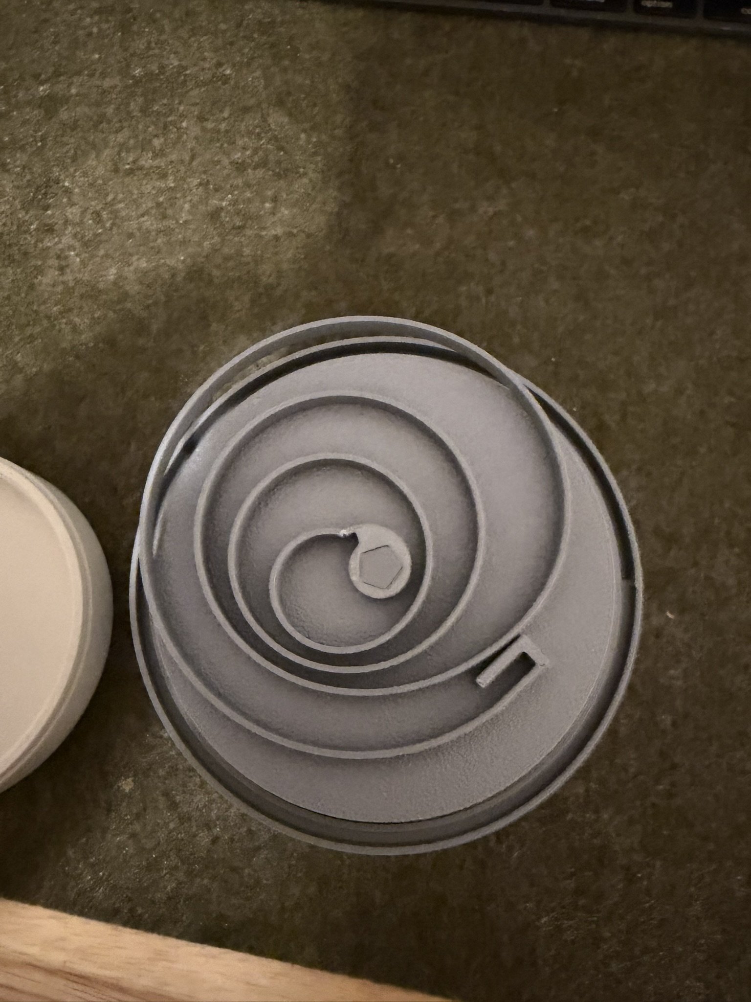
Spool Wheel
Tall enough to accept top screw + torsion spring
Center recess for torsion spring
Free-handed ratchets - this will be largely based on feel of mechanism
Pawl + Spring Mechanism
Pawl Shape will change based on feel
Grodded layout to determine angle / amount of torsion needed to interface pawl with teeth
Test Print 1 Goals:
Figure out proper tensioning of pawl
Determine if spring interface with wheel is sifficient + Durable
Make sure M3 screw / insert work properly
Sort out how to lock one end of the cable so the retractible portion remains on one side.
Figure out of tolerances for moving components ok
Possible use of bearings if necessary will require a redesign
Changes from V1
Opting for a side entry design to reduce bulky design
Integrating spring within spool wheel instead of stacked design